
Overview
The thought behind the LivelyButton is to explore spatial co-locatedness. It is a simple construct of a capacitive sensor controlling two RGB LED-strips connected to an Arduino board, and a stepper motor connected to another Arduino board via a motor shield. The motor spins two metal spirals below the surface of a semi-transparent fabric on the top-side of a wooden black box.
A sliding potentiometer can be used to set the sensitivity of the capacitive sensor so the LivelyButton reacts just before and at touch. When activated, the Arduino master board sends a cyclic pattern of PWM signals to the LED-strips, backlighting the soft surface in interplay of light and spiraling shadows. At the same time, the master board communicates to the motor board via serial port, and the motor spins the metal spirals under the soft surface accompanied by vibrations and the sound of the motor.
Over-time behavior
The LivelyButton has promoted relevant discussions and inspiration regarding co-location. A modified version was developed, which considered different visual and tactile feedback behaviors depending on the type, degree and length of the touch-interaction. A push button is used to change between three modes, and an RGB led displays the current mode.
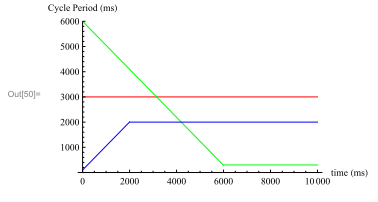
The ”Red” mode is the original ”constant” behavior, where the speed of light patterns change and the speed of the motor remains constant.
The ”Green” mode is the ”slow->fast” behavior, where the speed of light patterns change and the speed of the motor increase the longer the LivelyButton remains activated (touched).
The ”Blue” mode is the ”fast->slow” behavior, where the speed of light patterns change and the speed of the motor decrease the longer the LivelyButton remains activated (touched).
LivelyButton Behaviors
Materials
For the LivelyButton Box
- 1 wooden box
- 3 pulleys with motor-shaft adapters
- 1 belt for the pulley system
- Arduino board
- 1 12V Power supply
- 2 x RGB LEDstrip sections
- Stepper motor
- Arduino motor shield
- 2 spiral shaped thick springs
- 1 MOhm resistor (for capsense)
- 2 x 100pF capacitors (for capsense)
For the control box:
- 100 KOhm linear potentiometer to set the sensitivity
- 1 push button
- 1 RGB Led or three leds of different colors
Software
To program LivelyButton is necessary to use the Arduino IDE. The software for LivelyButton can be found here.